Demystifying the H-Bridge in Proportional Valve Driver Circuits
Understanding the Basics of Proportional Valve Drivers
What is a Proportional Valve Driver?
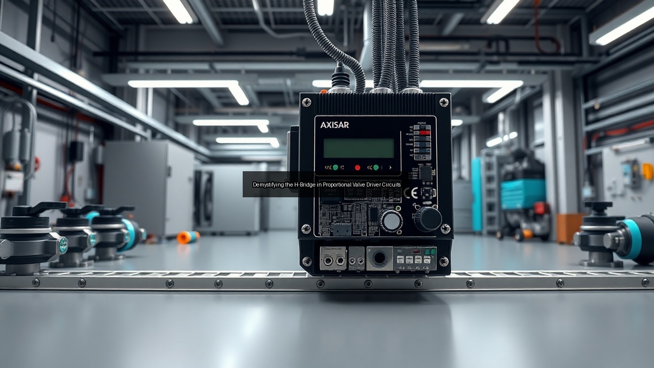
A proportional valve driver delivers precise current control to solenoids inside hydraulic valves. Engineers rely on this electronics module to regulate flow and pressure without abrupt on-off switching. The driver converts input signals into smooth coil excitation that matches commanded valve position. Users program parameters through potentiometer adjustments or digital interfaces on a compact PCB. North American manufacturers mount these units on DIN rail for easy integration into control cabinets. Proper driver selection improves response time and reduces energy losses across the hydraulic circuit. Systems often incorporate SAE J1939 communication to coordinate multiple valves on heavy equipment.
Key Components of Proportional Valve Circuits
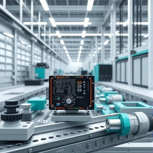
Each proportional valve circuit combines a solenoid coil, power stage, and feedback sensors. The coil generates magnetic force that shifts the spool inside the valve body. Analog amplifiers boost low-level command signals to the levels needed for accurate current regulation. A potentiometer on the driver board sets maximum output while protection circuits guard against short circuits and over-temperature faults. Modern designs add a 4 LED status array that shows power, fault, and communication states at a glance. DIN rail mounting keeps wiring tidy and allows quick replacement during maintenance. These elements work together to deliver repeatable performance in demanding hydraulic environments.
The Role of H-Bridge in Valve Control
The H-bridge sits at the heart of bidirectional valve control. Four power switches arranged in an H pattern let the driver reverse voltage polarity across the solenoid coil. This reversal enables the valve spool to move in both directions from a single supply rail. Engineers configure dead-time and PWM frequency to minimize heat while maintaining smooth current flow. The topology also supports rapid current decay modes that improve valve dynamics during deceleration. When paired with current sensing, the H-bridge closes the loop and compensates for coil resistance changes caused by temperature. Robust H-bridge designs withstand the inductive kickback inherent in solenoid loads.
The Functionality of H-Bridge in Proportional Valve Driver Circuits
How H-Bridge Circuits Work
H-bridge operation begins when the microcontroller commands two diagonal switches to conduct. Current then flows through the coil in one direction, shifting the valve spool accordingly. Toggling the opposite diagonal pair reverses current and spool motion. PWM modulation varies the average voltage applied to the coil while current feedback maintains the desired level. Shoot-through protection and proper gate drive timing prevent simultaneous conduction of both high-side and low-side devices. The resulting waveform produces smooth proportional movement rather than the jerky action typical of simple on-off drivers. Designers test the full bridge under load to verify thermal margins and electromagnetic compatibility.
Controlling Coil Voltage and Current
Precise coil current determines valve opening and therefore hydraulic flow. The driver measures voltage across a sense resistor and adjusts PWM duty cycle hundreds of times per second. Supply voltage variations and coil resistance drift receive automatic compensation through closed-loop control. Peak-and-hold profiles reduce power dissipation after initial spool movement. Over-current limits protect both the solenoid and the H-bridge MOSFETs during fault conditions. Engineers fine-tune ramp rates and dither amplitude directly on the driver board to eliminate spool stiction. These adjustments translate into stable pressure and flow characteristics across the entire operating range.
Using Analog Amplifiers in H-Bridge Circuits
Analog amplifiers translate command voltages or currents into the gate signals required by the H-bridge MOSFETs. High common-mode rejection keeps noise from affecting the feedback loop. Gain and offset trimmers on the amplifier stage allow calibration to specific valve coils. The linear front end preserves signal integrity when the proportional valve driver receives 0–10 V or 4–20 mA commands from a PLC. Temperature-stable components maintain calibration over wide ambient swings common in mobile hydraulic applications. When digital processing is added, the analog path still provides the fast inner current loop that digital loops alone cannot match at high PWM frequencies.
Integrating Modern Technologies with Proportional Valve Drivers

Incorporating USB Interfaces for Communication
USB connectivity turns a basic proportional valve driver into a configurable smart module. Technicians connect a laptop and upload new current limits, ramp times, or dither settings without removing the unit from the DIN rail. Firmware updates occur through the same port, extending product life as control strategies evolve. Data logging of coil current and temperature helps diagnose intermittent hydraulic problems. The interface also supports virtual potentiometer adjustment when physical access to the board is restricted. USB-C connectors now appear on newer designs, offering reversible orientation and higher data rates for rapid parameter sweeps during commissioning.
The Role of NFC in Valve Control
Near field communication lets technicians read and write driver parameters with a smartphone tap. NFC removes the need for physical cable connections in dusty or hard-to-reach enclosures. Each valve stores its calibration data in non-volatile memory accessible through near field communications. Operators confirm valve identity and firmware revision before entering hazardous zones. The same link can trigger a built-in self-test sequence that reports coil resistance and amplifier health. NFC complements SAE J1939 networks by providing a secondary, low-power channel for configuration and diagnostics during maintenance stops.
Digital Display and Feedback Mechanisms
A digital display mounted on the driver housing shows real-time coil current, command value, and fault codes without additional tools. Four LED indicators supplement the display by signaling power, enable, communication activity, and error states. Users scroll through menus with a single pushbutton to adjust parameters when a computer is unavailable. The display also provides visual confirmation that the H-bridge is delivering the commanded current to the solenoid. Integrated diagnostics reduce troubleshooting time on large hydraulic carts or test stands where multiple valves operate simultaneously.
Applications and Use Cases of Proportional Valve Drivers
Hydraulic Systems in North America
North American OEMs specify proportional valve drivers for construction equipment, agricultural machinery, and industrial presses. DIN rail mounting simplifies retrofits inside existing electrical panels. Drivers must survive wide temperature swings and high vibration while maintaining precise flow control. Axiomatic modules appear frequently on these platforms because of their robust H-bridge output stages and CANbus options. Local distributors stock common configurations to support fast field repairs. The result is tighter process control and lower energy consumption across diverse hydraulic circuits.
Pulsar and Atos Proportional Valves
Pulsar valves from Atos require matched electronics to reach rated performance. Their integrated coil designs pair cleanly with compact H-bridge drivers that deliver accurate current regardless of supply voltage fluctuations. Atos units often include LVDT feedback that the driver closes around for true position control. Calibration routines stored in the driver memory ensure interchangeability between valves on the same machine. Field technicians appreciate the USB and NFC options that allow parameter cloning from one valve to another without drawings or laptop access. These pairings dominate European and North American mobile hydraulic markets.
Real-World Examples of Proportional Control
A refuse truck uses proportional valve drivers to modulate packer blade speed and prevent sudden pressure spikes. The H-bridge reverses coil current quickly when the operator commands retract, improving cycle time. Another installation on a CNC press brake employs the same driver family to regulate ram approach speed, reducing part-to-part variation. In both cases the digital display and USB interface speed commissioning and allow operators to store job-specific profiles. Maintenance teams rely on NFC to read fault history during brief service windows, keeping equipment productive.
Frequently Asked Questions about Proportional Valve Drivers
What are the benefits of using an H-Bridge?
An H-bridge supplies bidirectional current from a single power source, eliminating the need for dual supplies or mechanical reversing contacts. This topology reduces wiring complexity and improves reliability in mobile hydraulic systems. Fast current reversal shortens valve response time and enables active braking of the spool. Integrated current sensing inside the bridge protects the solenoid coil and MOSFETs while delivering the precise force required for proportional control. The design also supports multiple decay modes that optimize efficiency and electromagnetic emissions across different valve types.
How to choose the right proportional valve electronics?
Start by matching driver output current and voltage ratings to the valve coil specifications. Verify that the H-bridge supports the required PWM frequency and current regulation accuracy. Check available interfaces such as USB, NFC, or SAE J1939 against your control architecture. Consider environmental ratings for temperature, vibration, and ingress protection when the unit mounts near the valve on a hydraulic cart. Review diagnostic features including the 4 LED array and digital display that speed troubleshooting. Finally, confirm that the supplier provides configuration software and documentation that match your commissioning workflow.
What are common issues with proportional valve driver circuits?
Over-temperature shutdowns occur when coil resistance rises with heat or when ventilation around the DIN rail enclosure is blocked. Incorrect dither settings cause spool oscillation that appears as pressure ripple in the hydraulic system. Ground loops between the driver and the machine controller introduce noise that destabilizes the current loop. Poorly tuned ramp rates produce jerky valve motion and accelerate mechanical wear. Intermittent USB or NFC connections usually trace to damaged connectors or firmware mismatches. Regular inspection of wiring and recalibration with the potentiometer or software interface prevents most field failures.
See Also
- From Concept to Creation Designing Your Own Proportional Valve Driver PCB
- Unlocking Precision with Proportional Valve Drivers for Hydraulic Systems
- The Future of Fluid Control Exploring Proportional Valve Electronics
- Integrating USB Technology with Proportional Valve Drivers for Enhanced Functionality
- How to Choose the Right Proportional Valve Driver for Your Application